M-PHY TX Essentials
The Tektronix M-PHY TX Essentials Test software runs on Tektronix real-time oscilloscopes that are based on Windows 7 computer operating systems. M-PHY TX Essentials provides support for all the base measurements for Spec 3.1 & CTS 3.1 within DPOJET framework, a state of the art tool designed for jitter analysis and core measurements. This solution is designed for engineers doing characterization and margin testing of the device. The solution is supplemented with MOI which provides guidance to users to setup the test and scope to accomplish specific measurements.
M-PHY TX Automated
The Tektronix M-PHY TX Automated Test software runs on Tektronix real-time oscilloscopes that are based on Windows 7 computer operating systems. M-PHY TX Automated provides support for 100% of tests as per Spec 3.1 & CTS 3.1 using TekExpress 4.0 framework, a state of the art tool designed for automation. The backend engine of automation is Iron Python based which uses socket based programming. This solution is designed for engineers doing verification and validation as per the CTS.
Key Features for M-PHY Transmitter testing
- 100% Test Coverage for all modes, gears, and data rates for HS, PWM, and SYS mode with M-PHY Essentials and M-PHY TX (Automated)
-
Option M-PHY Essentials enables full customization and comprehensive characterization, debug and analysis using setup libraries and MOI in DPOJET; the state of the art jitter analysis and debugging tool
- Automation support and scripting interface with Iron Python which supports socket based programming and .NET remoting interface
- M-PHY TX Automated User-defined mode allows modifying every parameter of different HS, PWM, and SYS tests, for comprehensive debug analysis and characterization
- Automated testing reduces the complexity of executing transmitter tests and enables you to test devices faster
- Selection of different Gears and Subgears of HS, PWM, and SYS signals, large/small amplitudes, impedance terminated/un-terminated
-
Full Contour Extrapolated eye diagram for BER analysis in steps at E-6 to E-10
- Ability to extrapolate further to E-12 and beyond for margin testing
- HS Gear 1 Mask Dynamic Movement to provide optimum eye opening as per Spec 3.1
- Accumulation of 3 M UIs in a single acquisition reducing test times for analysis
- Ability to embed/de-embed using filter files to enable mid bus probing
- Support for tri mode probes for single ended and differential signaling probing using Industry lowest noise probe P76xx series
- Manual mode testing for multi lanes
- Highly optimized setup performs Power Spectral Density (PSD) tests using oscilloscope-integrated algorithms uniquely, and does not require an external spectral analyzer or extra hardware to perform PSD measurements
- Single printable report for all tests across different combinations, provides pass/fail summary table, along with margin details, optional waveform captures, and eye diagrams. Available in (.mht and pdf)
Applications
The Physical layer is implemented for various high-speed serial interfaces (chip to chip communication) inside mobile devices. The common interfaces which utilize the M-PHY solution are:
- RFIC & modem interfaces in mobile devices
-
Companion chip interface with application processor over Unipro/SSIC
- Storage over UniPro/UFS
M-PHY transmitter testing with M-PHY TX
Single-button automated M-PHY transmitter testing
Once the test bench is set up and the DUT is properly connected, simply press the Start button to perform the selected test suite.
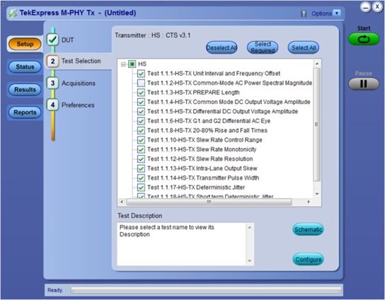
Single-button Automated M-PHY Transmitter testing
Automated transmitter testing saves time and resources
You do not need to be an expert on testing procedures. Remembering the exact steps to take each measurement is time consuming and often requires going back to the M-PHY specifications. M-PHY TX takes the guesswork out of conducting M-PHY Transmitter testing.
Even if you remember how to use the test equipment, it is common for even the most experienced operators to forget steps in the procedure or to set up the correct parameters, such as applying the correct signal impairments for a given test. M-PHY TX allows engineers to simply select the desired tests to run, and then work on other tasks while the tests are being executed.
Simple setup, test execution, and reporting
Test setup and test execution is very simple with the M-PHY TX Automated software. The test setup connections are very minimal, as it involves only one-piece of equipment for M-PHY TX. The TekExpress software provides a Graphical User Interface (GUI) and an intuitive workflow through setup and testing.
Setting up the bench
When setting up a test, nothing can be simpler than hooking up the test system by looking at a schematic. View the schematic of the selected test with a click of a button.
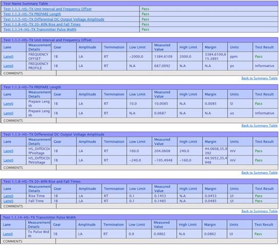
Pass/fail report
The M-PHY TX Report tab provides a single printable report of all the tests along with a Pass/Fail summary table, margins, and optionally waveform screen captures, eye diagrams, histograms, bathtub charts, etc.
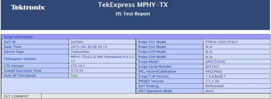
Test Report
M-PHY transmitter testing with M-PHY Essentials
DPOJET software with Option M-PHY provides the essential set of M-PHY Transmitter measurements with greater flexibility in the test setup. Like D-PHY Essentials on DPOJET, M-PHY Essentials also enables Characterization, Debug, Analysis, and Conformance testing of M-PHY designs.
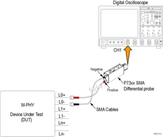
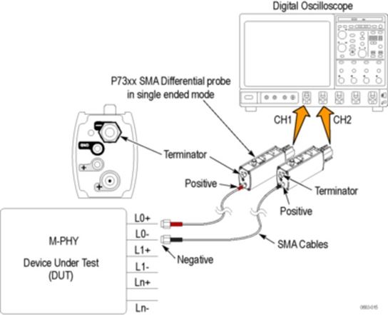
M-PHY Transmitter testing with M-PHY TX using Single-ended/Differential probes
100% M-PHY High Speed transmitter test coverage
M-PHY Essentials supports complete measurements to be performed in High Speed mode. It includes unique measurements such as Power Spectral Density on the real-time oscilloscope itself, which is a patent-pending methodology supported by Tektronix. Other solutions in the market require additional hardware to perform this test.
M-PHY Essentials slew rate measurement can be extended to slew rate resolution measurement.
Transmitter Eye Diagram measurement
M-PHY HS G1 requires an auto adjust of the mask shape based on eye opening. The following image shows how the eye mask adjusts itself based on the eye opening.
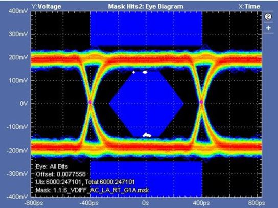
Transmitter Eye diagram measurement for HS G1 with Mask Hits
The mask automatically adjusts itself and reshapes based on the available eye opening and passes the eye diagram test.
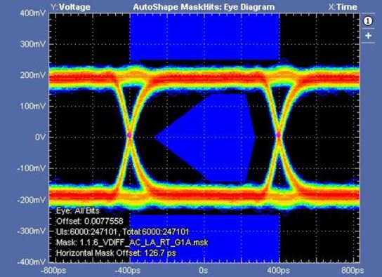
Transmitter Eye diagram measurement for HS G1 Auto shape to adjust mask hits and optimal eye opening
For M-PHY HS G3, the mask is defined like a diamond shape as shown below. For M-PHY Eye diagram prorated parameter values for a BER of 1E-6.
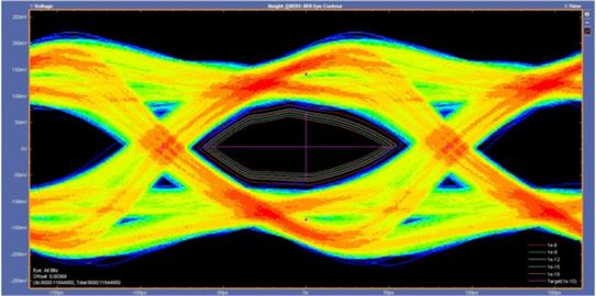
Transmitter Eye diagram measurement for HS G3 with BER contour
For HS G3B the eye diagram shows the accumulated eye at BER E-6 and extrapolated eye at various values in contour format. The extrapolated eye is at BER of 1E-10. Tektronix provides the unique ability for extrapolation using contours. This provides the designers the level of confidence of their design, a good perspective on margin for their designs and allows them to accomplish this task in less time without having to accumulate the eye at BER-10.
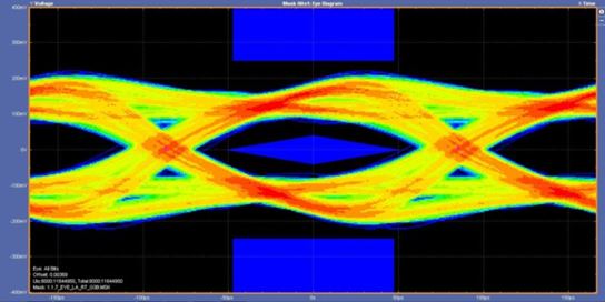
Transmitter Eye diagram measurement for HS G3B
Embed/De-embedding for Mid-bus probing
For M-PHY TX testing, measurements are specified at the TX pins. Many a times, the users measure signals at the end of the channel to view the effect at the RX pins or some test point in the middle of the channel (Mid-bus probing). For conformance testing, to ensure that the values meet the CTS, there would have a need to embed and/or de-embed channel to make measurements at the pin.
TekExpress Automated software allows you to do mid-bus probing via embedding/de-embedding signal path using filter files. You can use the 'Filter Setup' option in DUT panel to add the filters. This setting will be applied globally to all the measurements during acquisition.
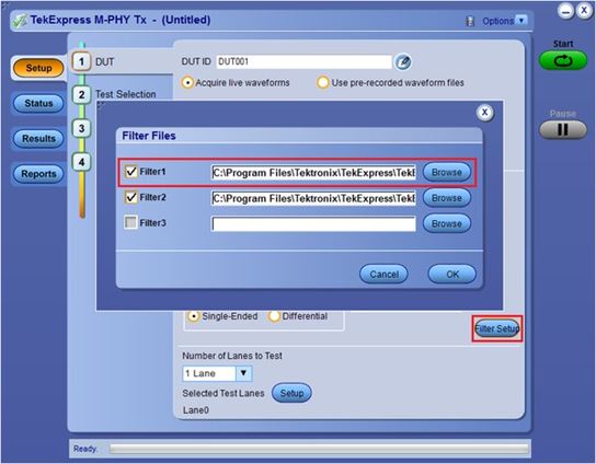
Filter Selection
Probing needs for M-PHY
The requirements for measurement equipment used to test conformance of an M-PHY transmitter running in High Speed mode is summarized below.
| Requirement | Performance |
|---|---|
| Return Loss | Per specification limits |
| Differential termination | 100Ω across input |
| Common mode termination | Infinite or consistent value |
| Rise Time | 3X fastest signal rise time |
| Sensitivity | 200-300 mVFS capability |
| Noise | Minimal added noise, (<1 or 2 mVrms desirable) |
| Attenuation | Smallest attenuation possible (1X desirable) |
The MIPI M-PHY standard presents significant challenges for oscilloscopes and probing. These challenges result in stringent requirements for HS-MODE measurements. SMA style probes with 50Ω inputs have been shown to yield superior results compared to high impedance probe approaches, particularly for HS-GEAR3 speeds. M-PHY CTS has been updated to list support for “SMA probe” type probing solutions. Tektronix SMA probes like the P7633 are unique in that and they can meet the requirements of M-PHY testing and introduce lower noise than the other oscilloscope probes.
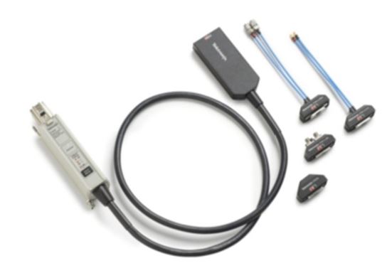
Tektronix P7633 SMA probe